


Medical Waste disposal Module
1 . General information.
The EK-75-40KT medical waste thermal neutralization plant is an industrial container-type complex for the thermal neutralization of hazard class 1 waste in accordance with Directive 2008/98/EC “Waste Framework Directive” and according to the list of hazardous properties 2000/532/EC, having properties classified as HP3, HP4. HP,5, HP6, HP7, HP8, as well as medical and biological waste according to the classification of medical waste 2014/955/EU;
- needles AND BLADES EWC 18.01.01,
- waste from EWC operations and procedures on 18.01.02,
- blood and its derivatives EWC 18.01.03,
- infectious waste EWC 18.01.04,
- waste containing tissues, organs or other biological samples EWC 18.01.05,
- remains of MEDICINES EWC 18.01.08,
- sanitary chemicals and toxic substances EWC 18.01.07,
- residues of medicinal and other chemicals EWC 18.01.06.
The EK-75-40KT installation is not intended for the disposal of large-sized products (without preliminary crushing), mercury-containing waste, explosive waste and prohibited for incineration by the manufacturer.
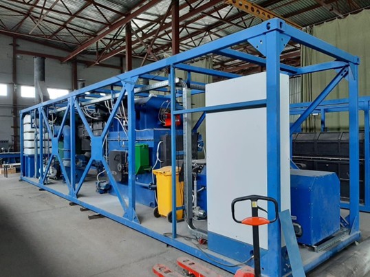
The technological equipment of the EK-75-40KT Installation is housed in modular structures in the dimensions of standard 40-foot shipping containers (2350 ×12036 × 2392 (h)). The installation will be installed on a site with a flat solid base, it can be placed on road slabs or floor slabs.
The installation is delivered to the customer in full factory readiness, with fully installed technological equipment, interior lighting, power electrical equipment, instrument control system and automation.
For operation, the EK-75-40KT installation requires connection to external utility networks (electricity, gas, and water supply). The installation is equipped with gas burners as standard. At the request of the customer, the Installation can be equipped with liquid fuel burners.
The EK-75-40KT installation is equipped with the necessary instrumentation and automation tools that allow you to control technological parameters, as well as control the process automatically or manually from the control panel.
Automation tools provide equipment protection by blocking when the specified technological parameters deviate from the regulated values, as a result of which failures or premature wear of the equipment may occur.
- needles AND BLADES EWC 18.01.01,
- waste from EWC operations and procedures on 18.01.02,
- blood and its derivatives EWC 18.01.03,
- infectious waste EWC 18.01.04,
- waste containing tissues, organs or other biological samples EWC 18.01.05,
- remains of MEDICINES EWC 18.01.08,
- sanitary chemicals and toxic substances EWC 18.01.07,
- residues of medicinal and other chemicals EWC 18.01.06.
The EK-75-40KT installation is not intended for the disposal of large-sized products (without preliminary crushing), mercury-containing waste, explosive waste and prohibited for incineration by the manufacturer.
The technological equipment of the EK-75-40KT Installation is housed in modular structures in the dimensions of standard 40-foot shipping containers (2350 ×12036 × 2392 (h)). The installation will be installed on a site with a flat solid base, it can be placed on road slabs or floor slabs.
The installation is delivered to the customer in full factory readiness, with fully installed technological equipment, interior lighting, power electrical equipment, instrument control system and automation.
For operation, the EK-75-40KT installation requires connection to external utility networks (electricity, gas, and water supply). The installation is equipped with gas burners as standard. At the request of the customer, the Installation can be equipped with liquid fuel burners.
The EK-75-40KT installation is equipped with the necessary instrumentation and automation tools that allow you to control technological parameters, as well as control the process automatically or manually from the control panel.
Automation tools provide equipment protection by blocking when the specified technological parameters deviate from the regulated values, as a result of which failures or premature wear of the equipment may occur.
2 . The main technical characteristics of the EK-75-40KT Installation
Name of the parameter
Values
Category of the room (container module) for explosion and fire hazard
G
Standard MSW productivity (with an average caloric content of 2500 kcal/kg and W=0%), not more than, kg/h
75
Operational productivity for declared waste (estimated caloric content 3625 kcal/kg, W=20%, not more than, kg/h
60
The kind of fuel used to maintain gorenje
Specific consumption of diesel fuel, kg of fuel/kg of waste
0,12÷0,14*
Specific consumption of gaseous fuel, m3 of gas/kg of waste
0,15÷0,18*
Waste incineration temperature, K (C)
10733…1123 (800…850)
Waste incineration temperature, K (C)
1273…1373 (1000…1100)
Maximum exhaust gas temperature, K (C)
523 (250)
Type of current, frequency and voltage of alternating current
Three-phase, 50 Hz, 380 V
Total power consumption, kW, no more than
32
Weight of the installation assembly, kg (one installation)
12 500 (+10%)
The content of harmful substances in the exhaust gases at the chimney section, mg/m3
In accordance with EU requirements
The content of harmful substances in the ash residue, mcg/kg, no more:
- benzpyrene
- polychlorobiphenyls
0,002
2,2
O2 content in combustion chamber flue gases, %
6-12
The volume of flue gases. m3/h at present.
473
Water consumption for cooling and cleaning of flue gases, m3/h, max
0,2
Flue gas cleaning reagent
Slaked lime
Lime consumption, kg/h, not less
1,53**
Number of service personnel, people/shift
*) – The indicator is being refined during the NDT process;
**) – The indicator is specified during field measurements.
3. A brief description of the device and operation of the EK-75-40KT Installation.
The installation is a set of technological and auxiliary equipment that ensures the loading of waste, its thermal neutralization, cleaning and removal of flue gases, unloading of ash (including volatile) and gas purification products. The control of the technological equipment of the complex is carried out in automatic or manual mode from the control panel. To control the technological parameters of the complex, the installation of instrumentation and control systems and an automated process control system is provided. The waste disposal process includes the following technological stages:
- waste supply for incineration;
- controlled thermal decontamination - incineration;
- chemical and mechanical cleaning of flue gases;
- transportation and removal of flue gases;
- ash unloading;
and auxiliary operations:
- waste collection;
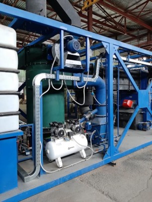
- preparation and supply of lime solution for the gas cleaning system;
- reception and storage of liquid fuel, reception and supply of gaseous fuel.
The installation is a set of technological and auxiliary equipment that ensures the loading of waste, its thermal neutralization, cleaning and removal of flue gases, unloading of ash (including volatile) and gas purification products. The control of the technological equipment of the complex is carried out in automatic or manual mode from the control panel. To control the technological parameters of the complex, the installation of instrumentation and control systems and an automated process control system is provided. The waste disposal process includes the following technological stages:
- waste supply for incineration;
- controlled thermal decontamination - incineration;
- chemical and mechanical cleaning of flue gases;
- transportation and removal of flue gases;
- ash unloading;
and auxiliary operations:
- waste collection;
- preparation and supply of lime solution for the gas cleaning system;
- reception and storage of liquid fuel, reception and supply of gaseous fuel.
Waste is delivered to a special installation site by specialized vehicles, in specialized containers with a volume of 120-240 liters on wheels, collected and packaged according to EU requirements. Medical and biological waste must be stored directly in bulk shipping containers before thermal decontamination in forcibly cooled rooms (cold rooms), cabinet refrigerators or refrigerated truck trailers.
The EK-75-40KT installation is equipped with a specialized mechanized loading device that ensures the reception, capture and tipping of a 120-240 liter shipping container into the receiving compartment of the loading device. Next, the intake compartment of the loading device is automatically closed with an airtight lid and the loading window of the incinerator opens, and medical or biological waste is fed into the combustion chamber by a special piston pusher. The device and the principle of operation of the automated loading mechanism exclude contact of the installation operator with the disposed waste. The mass of a one-time waste load into an incinerator depends on the calorific value of the waste being disposed of, but as a rule should not exceed 10-15 kg.
Incineration (thermal neutralization) The waste occurs in the combustion chamber of the Installation at a temperature of 800-250 ° C. The temperature of the technological process is maintained automatically by turning on/off the burner devices for additional fuel. To intensify the combustion process, atmospheric air is supplied to the combustion chamber by a blow fan.Gorenje The supply of atmospheric air ensures the complete combustion of the organic components of the waste. The combustion chamber of the Installation operates at a vacuum of 2-3 mm of water (20-30 Pa), which is created by a smoke extraction fan. Waste periodically neutralized in the combustion chamber is mixed with mechanical agitators.
The flue gases generated during waste incineration flow from the combustion chamber into the afterburning chamber of the Installation. The afterburning chamber is equipped with an additional burner device to maintain a set process temperature of 1000-1100 ° C and additional atmospheric air supply pipes for the final oxidation of possible organic components of flue gases coming from the combustion chamber. The geometric dimensions of the afterburning chamber ensure that the flue gases are exposed for at least 2 seconds.
After the afterburning chamber, the flue gases are supplied for cooling and cleaning. The gas purification scheme implemented in the Installation provides for mechanical and chemical purification of flue gases using the "semi-dry" method. Flue gas cleaning includes the following processes:
• physico-chemical reagent purification of flue gases from acidic components, namely HCl, HF, SO2(H2SO3), SO3(H2SO4), NO, NO2, consists in their adsorption on a solid sorbent (lime) followed by chemisorption, i.e. chemical transformation of these components into the corresponding dry salts on the surface sorbent in the volume of gas cleaning equipment. The dry sorption reactor installation consists of a hollow scrubber operating according to a semi-dry scheme with a supply device for process water and atmospheric air, a dry sorption reactor with a rotating perforated rotor filled with a nozzle and a fresh dry sorbent supply unit, a bag filter with a partially spent sorbent storage hopper and a device for returning part of the unreacted sorbent from the storage hopper to the contact the reactor zone. The rotor nozzle of the dry sorption reactor consists of freely moving ceramic balls.
• control mechanical cleaning of flue gases from solid components (fly ash, gas purification salts) is carried out using a bag filter equipped with a reverse pulse purge device for high-temperature fabric hoses.
The cooled and purified flue gases enter the transportation system. Flue gases are transported through flues connecting the technological devices of the installation with a smoke extraction fan. The cooled and purified flue gases are removed into the atmosphere by a smoke extraction fan through the chimney. The temperature of the flue gases at the outlet of the chimney must not exceed 250 ° C. The height of the chimney is at least 9 m (the diameter of the chimney is 430 mm).
The ash residue accumulating on the hearth of the incinerator combustion chamber is discharged mechanically by a screw conveyor. Ash formation is 15-20% by weight.