


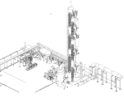
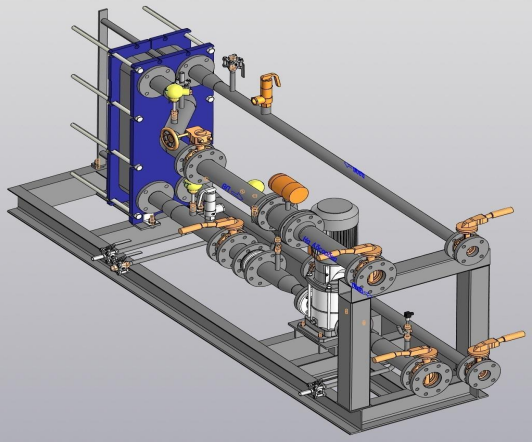
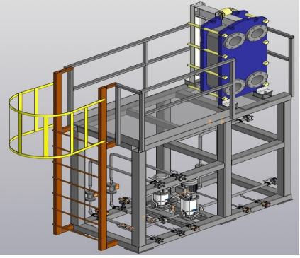
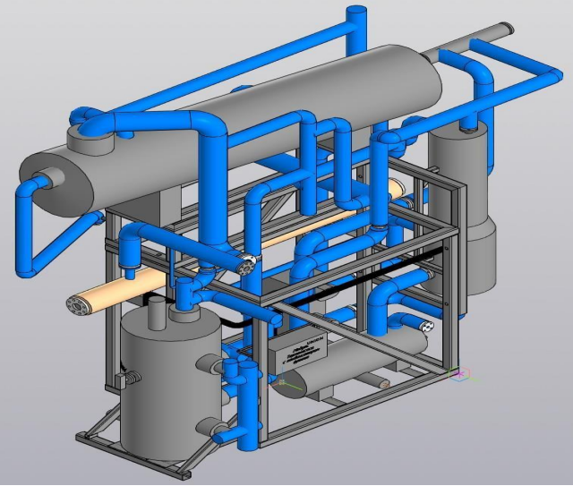
Layout of the EURI 2000 station
Nitrogen oxide removal unit (DeNOx)
In the DeNOx unit, nitrogen oxides are removed from the flue gas via a reaction in which ammonia is supplied as an aqueous solution, and compressed air is added to the nozzle to improve mixing and atomize the ammonia water. The amount of ammonia water supplied is controlled by an analyzer that measures NO concentration at the unit's outlet. The maximum NOx concentration in the flue gases at the catalysis unit entrance is 500 ppm. The automatic concentration stabilization point is 10 ppm.
Reboiler
From the DeNOx unit, flue gas enters the reboiler, where heat is used to generate the necessary desorbing energy for the installation. The desorbing energy can be regulated by the internal bypass of the reboiler.
Smoke exhauster
Pumping flue gas through the switchgears of the absorber column, creating a counterflow of smoke from the MEA.
Absorber
Here, the CO2 in the flue gas is absorbed by a 32% solution of MEA (monoethanolamine) passing in a countercurrent with the flue gas. The remaining flue gas leaves the open upper part of the absorber. To avoid MEA losses, the flue gas is washed and cooled in the washing section at the top of the absorber using circulating water, followed by a small additional washing section with fresh water.
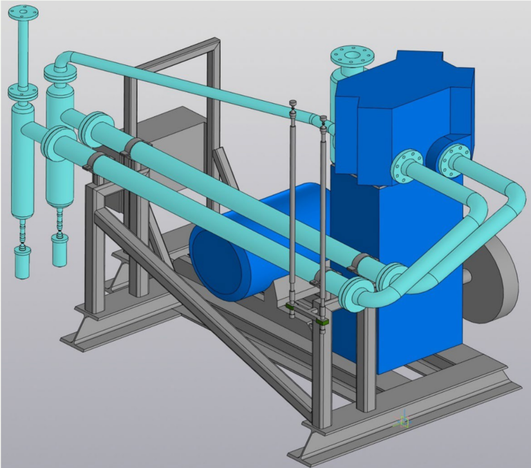
Heat exchange equipment assembly of the gas scrubber
The flue gas is then cooled to ambient temperature in a flue gas scrubber using water flowing in counterflow with the gas. The water is circulated by a pump and cooled in a plate heat exchanger using cooling water.
In this case, the operation of a reboiler using the thermal energy of flue gas is described. A steam reboiler can be used. This choice will be made after building a complete model of material flows, based on the technical data received from the customer.
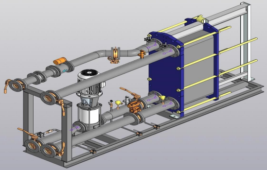
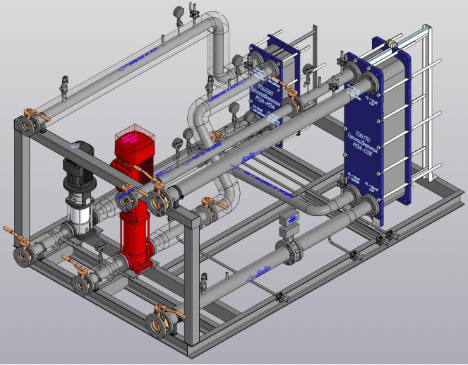
MEA heat exchange equipment unit
The MEA that has been absorbed by CO2 in the absorber (rich MEA) is pumped from the bottom of the absorber through a rich/poor MEA heat exchanger, where it is preheated before entering the desorber. In the desorber, CO2 is desorbed from the MEA using energy from the reboiler. Desorbed MEA (poor MEA) passes into the reboiler, where part of it evaporates, and back into the desorber in the form of a mixture of liquid and steam. The steam is used for desorption, and the liquid is pumped to the rich/poor MEA heat exchanger and the water-cooled MEA cooler before returning to the absorber.
The heat exchange equipment unit of the small cycle absorber
The circulating water for the first washing section is pumped and cooled in a plate heat exchanger using cooling water.
Water scrubber heat exchanger unit
CO2 gas, together with excess steam from the desorber, exits through the upper part of the desorber via a small washing section and enters the gas cooler, where the steam condenses, and the gas is cooled. From the gas cooler, CO2 and condensate enter a water scrubber, where condensate is separated from the gas at the bottom and the gas is washed of any MEA residues and MEA degradation products using a weak stream of fresh water.
From the water scrubber, condensate and added fresh water are pumped into the flushing sections of the absorber and desorber.
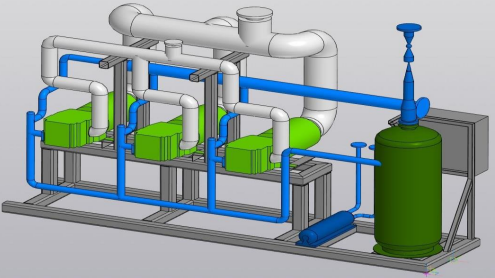
CO2 compressor unit
Then the gas goes to the CO 2 compressor group, where it is compressed to 15... 18 bar. The compressors are two-stage double-acting dry-running piston compressors with water-cooled intermediate and aftercoolers.
The compressor capacity is regulated by a valve-lift system that unloads half of the compressor capacity based on the suction pressure.
Moisture separator, dehumidifier, and carbon filter
After the compressors, the gas passes through a water separator cooled by a refrigerant, where it is cooled, and water is released into the condensate. A water separator with a coalescing element removes water condensate from the gas stream.
To condense CO2 gas, it is dried to a water content of approximately 10 ppm by volume in a dehydrator. The dryer consists of 2 columns, one in operation and the other in regeneration/standby mode. Each column is filled with a special desiccant (activated aluminum oxide), which, in addition to removing water, will also remove all oxygen-containing compounds, such as aldehydes and nitrogen dioxide. The dryer is automatically regenerated by gas from the top of the CO2 condenser.
This gas is heated by an electric heater. The regenerating gas is discharged into the atmosphere. The dew point sensor measures the dew point of the dehumidified CO2 gas exiting the dryer.
The dryer's operating cycle is 8... 16 hours of operation and 8... 16 hours of regeneration. The dehumidifier regeneration cycle consists of the following steps:
The column is in operation,
Column change,
Pressure relief,
Heating the desiccant layer with hot CO2,
Cooling of the desiccant layer with cold CO2,
Creating pressure in the column,
Standby mode before starting work. One non-regenerable carbon filter is installed after the dehumidifier. The filter will adsorb all odors that the dehumidifier does not capture.
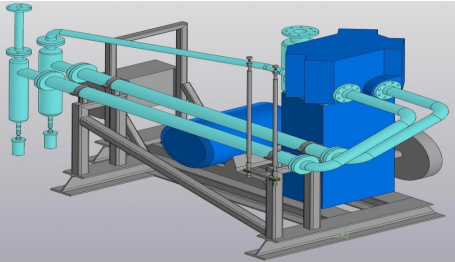
Refrigeration compressors
Compression of the gaseous refrigerant is performed by three single-stage screw compressors with an economizer port. The compressors are lubricated and cooled by oil circulated through a pressure difference across the compressor. The circulating oil is separated from the gas in the oil separator and cooled in a water-cooled cooler. The compressor capacity is controlled by the CO2 pressure in the distillation column.
Purifying unit
To ensure the highest possible CO2 purity, the plant is equipped with a liquid CO2 distillation purification system that removes non-condensable gases, including oxygen, nitrogen, methane, and hydrogen.
The CO2 gas from the carbon filter is passed through the CO2 reboiler of the purification unit, where it is cooled before entering the CO2 condenser, where most of the gas is liquefied at approximately —25°C. The CO2 condenser is cooled with a liquid refrigerant circulating in the refrigeration unit.
The purge gas for purifying is supplied from the CO2 reboiler. In the distillation column, liquid CO2 from the CO2 condenser contacts the gas from the reboiler, allowing separation of inert gases from liquid CO2. From the bottom of the distillation column, liquid CO2 is pumped into the storage tank through a heat pump.
The non-condensable gases, together with some CO2 from the top of the CO2 condenser, are used to regenerate the dryer and control air, or are removed.
This unit allows the production of gas with 99.99% purity.
In the DeNOx unit from the flue gas are removed oxides nitrogen via a reaction in which ammonia is supplied as an aqueous solution, and compressed air is added to the nozzle to improve mixing and atomize the ammonia water. The amount of ammonia water supplied is controlled by an analyzer that measures NO concentration at the unit's outlet. The maximum NOx concentration in the flue gases at the catalysis unit entrance is 500 ppm. The automatic concentration stabilization point is 10 ppm.
Reboiler
From the DeNOx unit, flue gas enters the reboiler, where heat is used to generate the necessary desorbing energy for the installation. The desorbing energy can be regulated by the internal bypass of the reboiler.
Smoke exhauster
pumping flue gas through the switchgears of the absorber column, creating a counterflow of smoke from the MEA.
Absorber
Here, the CO2 in the flue gas is absorbed by a 32% solution of MEA (monoethanolamine) passing in a countercurrent with the flue gas. The remaining flue gas leaves the open upper part of the absorber. To avoid MEA losses, the flue gas is washed and cooled in the washing section at the top of the absorber using circulating water, followed by a small additional washing section with fresh water.
Heat exchange equipment assembly of the gas scrubber
The flue gas is then cooled to ambient temperature in a flue gas scrubber using water flowing in counterflow with the gas. The water is circulated by a pump and cooled in a plate heat exchanger using cooling water.
In this case, the operation of a reboiler using the thermal energy of flue gas is described. A steam reboiler can be used. This choice will be made after building a complete model of material flows, based on the technical data received from the customer.
MEA heat exchange equipment unit
The MEA that has been absorbed by CO2 in the absorber (rich MEA) is pumped from the bottom of the absorber through a rich/poor MEA heat exchanger, where it is preheated before entering the desorber. In the desorber, CO2 is desorbed from the MEA using energy from the reboiler. Desorbed MEA (poor MEA) passes into the reboiler, where part of it evaporates, and back into the desorber in the form of a mixture of liquid and steam. The steam is used for desorption, and the liquid is pumped to the rich/poor MEA heat exchanger and the water-cooled MEA cooler before returning to the absorber.
unit of The heat equipment the small cycle absorber
The circulating water for the first washing section is pumped and cooled in a plate heat exchanger using cooling water.
Water scrubber heat exchanger unit
The CO2 gas, together with excess steam from the desorber, exits through the upper part of the desorber through a small flushing section and enters the gas cooler, in which the steam condenses and the gas cools. From the gas cooler, CO2 and condensate flow into a water scrubber, in which the condensate is separated from the gas in the lower part, and the gas is flushed from any residues of MEA and decomposition products of MEA using a weak stream of fresh water.
From the water scrubber, condensate and added fresh water are pumped into the flushing sections of the absorber and desorber.
Unit WITH 2 compressors
Then the gas goes to the group of CO2 compressors, where it is compressed to 15...18 bar isb. The compressors are two-stage double-acting dry-running reciprocating compressors with an intermediate and an end cooler with water cooling.
The performance of the compressors is regulated by the valve lifting system, which will unload half of the compressor capacity according to the suction pressure.
Dehumidifier, dehumidifier and carbon filter
After the compressors, the gas passes through a dehumidifier cooled by a refrigerant, in which the gas is cooled and water is released into condensate. A water separator with a coalescing element removes water condensate from the gas stream.
To condense the CO2 gas, it is drained to a water content of approx. 10 ppm by volume in a desiccant. The dryer consists of 2 columns, one is in operation and the other is in regeneration mode./expectations. Each column is filled with a special desiccant (activated alumina), which, in addition to removing water, will also remove all oxygen-containing compounds such as aldehydes and nitrogen dioxide. The dryer is automatically regenerated by gas from the top of the CO2 condenser.
This gas is heated by an electric heater. The regenerating gas is discharged into the atmosphere. The dew point sensor monitors the dew point of the desiccated CO2 gas coming out of the dryer.
The dehumidifier's operating cycle is 8...16 hours of operation and 8...16 hours of regeneration. The dehumidifier regeneration cycle consists of the following steps:
The column is in operation,
Column change,
Pressure relief,
Heating of the desiccant layer with hot CO2,
Cooling of the desiccant layer with cold CO2,
Creating pressure in the column,
Standby mode before starting work, One unregenerated carbon filter is installed after the dryer. The filter will adsorb all odorous substances that are not trapped by the desiccant.
Refrigeration compressors
Compression of the gaseous refrigerant is performed by three single-stage screw compressors with an economizer port. The compressors are lubricated and cooled by oil circulating through a pressure drop across the compressor. The circulating oil is separated from the gas in an oil separator and cooled in a water-cooled cooler. The compressor performance is regulated by the CO2 pressure in the distillation column.
Cleaning unit
To ensure the highest possible purity of CO2, the plant is equipped with a purification system based on the distillation of liquid CO2, which removes non-condensable gases such as oxygen, nitrogen, methane, hydrogen and others.
The CO2 gas from the carbon filter is passed through the CO2 reboiler of the purification unit, in which the gas is cooled before passing into the CO2 condenser, where the bulk of the gas is liquefied at a temperature of approx. –25 °C. The CO2 condenser is cooled by a liquid refrigerant circulating in the refrigeration unit.
The purge gas for cleaning is supplied from the CO2 reboiler. In the distillation column, the liquid CO2 from the CO2 condenser comes into contact with the gas from the reboiler, thereby allowing the inert gases to be separated from the liquid CO2. From the bottom of the distillation column, liquid CO2 is pumped into a storage tank via a heat pump.
The non-condensable gases, together with some CO2 from the top of the CO2 condenser, are used to regenerate the dryer and control air or are removed.
This unit allows to obtain 99.99% purity of the produced gas.
Cooling system
The unit is cooled with cooling water or an ethylene glycol solution. The cooling water circulates under the influence of pressure drop across various consumers of cooling water in the installation:
Cooling water:
Flue Gas Scrubber Cooler
Cooler of the absorber flushing section
The MEA Cooler
Gas Cooler
Blocks of CO2 compressors
Refrigeration compressor unit
Refrigerant condenser
Water treatment system
It is used to obtain demineralized water used in a water scrubber and further to stabilize the MEA solution.
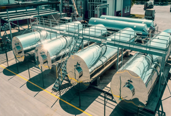
Long-term storage system
The long-term storage system includes a fleet of storage equipment, which is installed on an outdoor site. A refueling unit for transport containers is included. Attention: The installation and operation of this system is subject to the rules of operation of the OPO. The final volume of the storage equipment is determined by the customer (station capacity + finished product sales plan).
Main production parameters
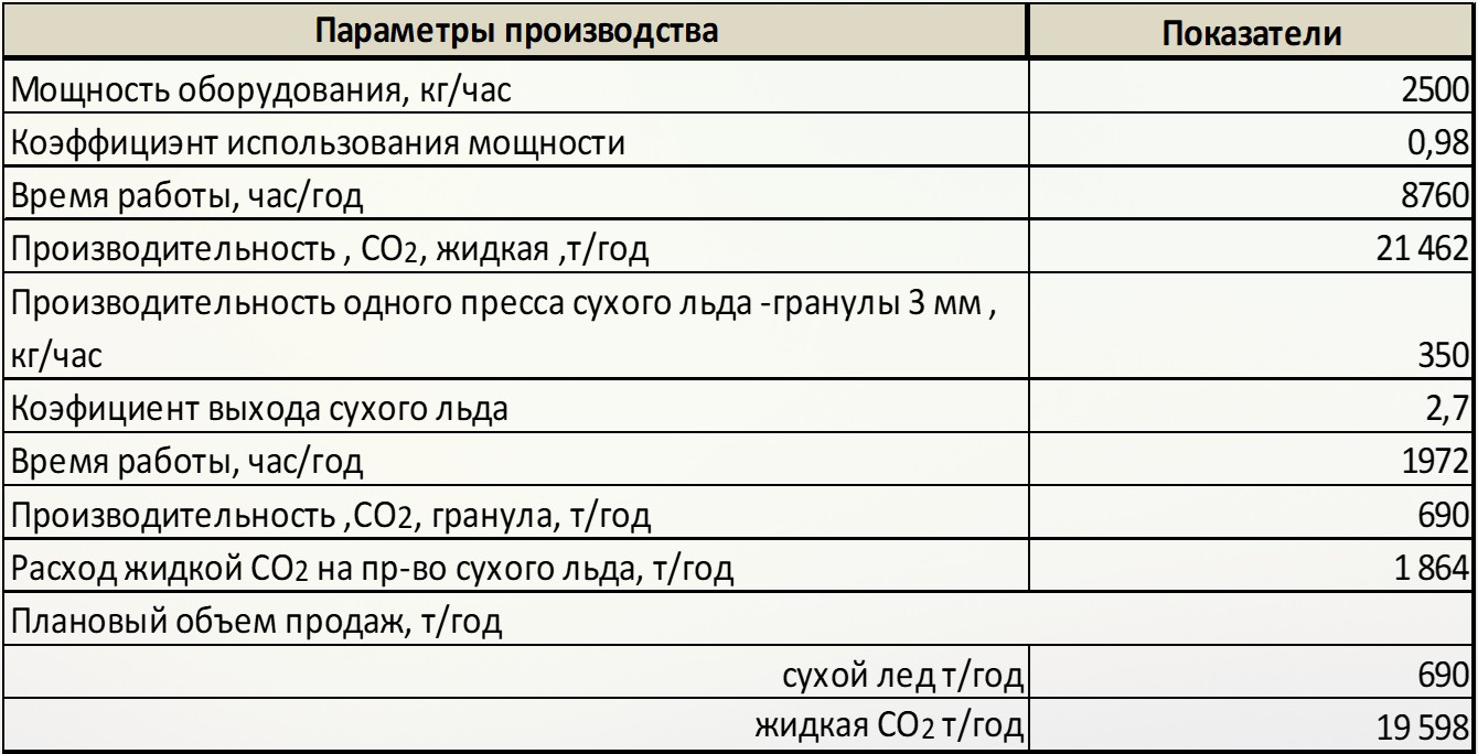
Workshop for the production of liquid carbon dioxide
Name
The standard,
m3/hour
For the production of demineralized water
3,50
For feeding open cooling towers
4,20